2.4 More Systems Architecture Dimensions
Architectural visions are however not the only architectural dimensions of a system. We shall now introduce a number of new dimensions that can be used to refine each architectural vision.
2.4.1 Descriptions versus Expected Properties
As already discussed in section 0.1, one must now recall that there exists two complementary ways of specifying a system. The first one refers to descriptions: in this specification mode, one explicitly1This is why descriptions are considered as specifications in extension. describes the behavior and structure, either of the system of interest (if one is reasoning functionally or constructionally) or of its environment (if one reasons operationally).
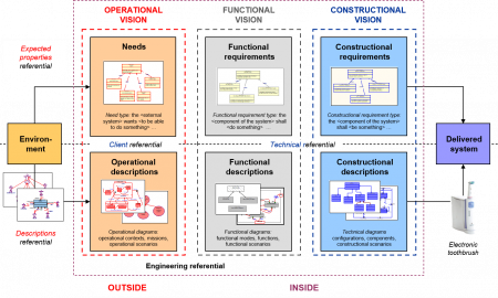
Figure 29 – Descriptions versus expected properties
The second way deals with expected properties: one is now not explicitly describing a system, but rather stating the (operational, functional and constructional) properties, expected/intended2This is why expected properties are considered as specifications in intention. to be satisfied by the system. Note these expected properties are usually called requirements in systems engineering (see section 0.1 for more details). This gives rise to the six different – but altogether exhaustive3This key property is ensured by the mathematical foundations of the CESAM framework (see Chapter 0) – specification modes that are presented in the below Figure 29, that is to say:
- For descriptions: operational descriptions, functional descriptions, constructional description,
- For expected properties: needs4We will use here the term “need” instead of “operational requirement”, even if they are equivalent. We indeed prefer to reserve the term “requirement” for functional & constructional uses in order to separate strictly the domain of the question (expressed with needs) and the domain of the solution (stated with requirements). , functional requirements, constructional requirements.
As explained in section 0.1, one can equivalently (from a purely theoretical point of view) completely specify any system by using either descriptions, or expected properties. However these two modes of specification are absolutely not equivalent from an engineering effort perspective (see again section 0.1). On one hand, descriptions are indeed well adapted to define and tosynthetize the behavioral & structural dimensions of a system. On the other hand, performances of a system are typical expected properties. But the converse is totally false. As a good practice, an efficient and optimal – in terms of engineering time spent – system specification shall mix descriptions (reserved for defining behavioral & structural elements and their dynamics) and expected properties (reserved for performance). This trick allows drastically reducing the requirements volume in a specification file, thus improving its readability, since descriptions are usually encoded by a huge amount of requirements.
2.4.2 Descriptions
Descriptions can be separated in four different views, each of them modeling a different dimension of a system. States are first modeling time. Static elements are then depicting the core objects of each architectural vision when dynamics are describing their temporal behavior. Flows are finally consolidating the exchanges involved in these dynamics. On should also note that all these system views are both exhaustive – they allow modeling completely a system – and non-redundant – each view provides a specific perspective which is not covered by the other views – due to the foundations of our system architecting framework (see section 0.1).
2.4.2.1 States
A state T associated with a given system S is modeling a period of time, that is to say a set consisting of one or more intervals of time, where the system S can be analyzed in a homogeneous way from the perspective of a given architectural vision. A state can be usually specified by its initiation and termination events5 T = ∪ [t1, t2] for all moments of time t1 and t2 such that an initiation (resp. termination) event occurs at t1 (resp. t2)., which are both modeling phenomenon occurring instantaneously, i.e. at a specific moment – not interval – of time. As one may imagine, the initiation (resp. termination) events do correspond to moments of time – the same type of event can indeed occur at different moments of time – where the period of time modeled by T begins (resp. ends).
States are used to model time. In each architectural vision, a key temporal analysis consists indeed in decomposing in different states the time line of a system from birth to death. In such analyses, one can then model the usual temporal behavior of a system as a succession of states in which lies the system, one after the other. Think for instance to a normal day of a human person which begins in the “Sleeping” state, passing then to the “Morning dress” and “Breakfast” states, before arriving to the “Transportation” and “Working” states, passing a new time in the “Transportation” state, then in the “Relaxing”, “Dining” and “TV listening” states, before going back again to the “Sleeping” state. We will discuss more precisely in Chapter 4 that kind of analysis for systems, based on states.
There are therefore logically three different types of states for any given system S, depending on the considered architectural vision, which are defined as follows:
- Operational states are called operational contexts: an operational context for S is a period of time OC(S) characterized by the fact that external interactions of S during OC(S) do only involve a certain fixed set of stakeholders or external systems of its environment.
- Functional states are called functional modes: a functional mode for S is a period of time FM(S) which is characterized by the fact that the behavior of S during FM(S) can be modeled by only using a certain fixed set of system functions.
- Constructional states are called (technical) configurations: a configuration for S is a period of time TC(S) – usually identified with the involved components – characterized by the fact that the structure of S during TC(S) does only consist of a certain fixed set of system components.
In other terms, one changes of operational context, functional mode or configuration if and only if a new stakeholder, function or component appears within the life of a given system. Passing from the “Rainy” to the “Sunny” operational context typically means that the Rain stakeholder disappeared and was replace by the Sun stakeholder. Replacing stakeholder by function or component would then lead to similar examples for the two other types of states that we introduced.
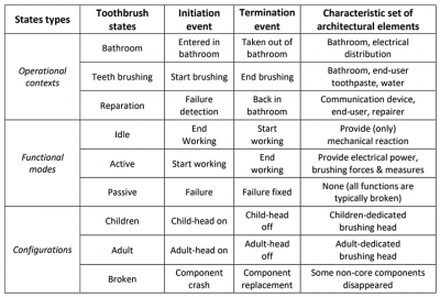
Table 2 – Examples of states for an electronic toothbrush
Table 2 illustrates the notion of states with some examples for an electronic toothbrush, where we explicated the set of architectural (static) elements characterizing each state. One can see on these examples that there is no one-to-one correspondence between these different states. The toothbrush can indeed typically be in the “Bathroom” operational context and in either an “Active” or a “Passive” functional mode (in that last case, it would mean that the toothbrush is broken, but that the user did not noticed it) and in either a “Children” or an “Adult” configuration. In the same way, the toothbrush can be in the “Active” functional mode, but in either a “Bathroom” or a “Reparation” operational context (this last case corresponds to the situation where the toothbrush was repaired in the reparation workshop) and in lots of different configurations. The toothbrush may finally also be in a given configuration, but in various operational contexts or functional modes as one can easily check on the previous Table 2. These examples do thus show that each type of state may be allocated with many other types of states without any simple relationship in this matter.
Let us end by providing the standard representation of states – in most modeling languages – which are usually modeled by means of oval shapes, as one can see in the below Figure 30.
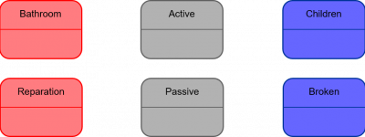
Figure 30 – Standard representations of states
2.4.2.2 Static Elements
A static element with respect to a given system S refers to an input/output mechanism associated with S from the perspective of a certain architectural vision. We are using the term “static element” to emphasize that this new system description does not focus on the temporal dynamic (see next sub-section for that other point) of the involved input/output mechanism, but provides just a nontemporized definition of such a mechanism without explicating its “algorithm”.
There are therefore logically three different types of static elements for a given system S, depending on the considered architectural vision, which are defined as follows:
- Operational static elements are called missions: a mission of S is an input/output behavior of the environment Env(S) of S, involving both S and other external systems.
- Functional static elements are called functions: a function of S is an abstract implementationindependent intrinsic input/output behavior of S, that is to say that only involves S.
- Constructional static elements are called components: a component of S formally refers to a concrete implementation-dependent intrinsic input/output behavior of S. A component of S is therefore naturally identified to a concrete part of S.
Missions shall never be mixed with functions or components, since they do not refer to the system of interest, but to its environment. Functions and components refer both to the system of interest, but in two different ways. Functions are indeed independent of any concrete implementation of the system of interest when components do always refer to its specific concrete implementation. There are thus two types of functions: on one hand, transverse functions that can only be implemented by using several components; on the other hand, unitary functions that can be implemented by using a single component (such functions are thus “simply” modeling the components behavior). Transverse functions are very important since they do model transverse system behaviors that, by definition, cannot be easily analyzed at constructional level. One may finally observe that the existence of such transversal (or equivalently emergent) behaviors is intrinsic to any system since it is directly the consequence of the emergence postulate (see Section 0.2).
Note also that the standard way for stating a mission or a function of a given system is to use the “To do something” pattern in both cases. The only difference lies in the subject associated with the verb that describes the mission or function. This subject shall consist in external systems or stakeholders in the case of a mission (“external systems cooperating with the system shall do something”) when it shall only be the system alone for a function (“the system shall do something”). On the other hand, components are usually stated using only names referring to concrete objects forming the system. Table 3 illustrates the notion of static elements with some examples for an electronic toothbrush. We provided some inputs and outputs for each proposed static elements.
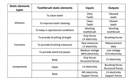
Table 3 – Examples of static elements for an electronic toothbrush
As already mentioned, static elements are related by allocation relations. Each function contributes for instance to one or more missions, which corresponds to the fact that a mission can be obtained by composing a function with some other input / output behavior (see the example given in note 84): such a situation is then expressed by saying that this mission is allocated to the considered function. In the same way, a component can contribute to a mission and/or a function, which will be expressed by saying that such a mission or function is allocated to the considered component.
We may also provide the standard representations of the three different types of static elements – in most modeling languages – which are usually modeled by circles for missions, ovals for functions and boxes for components, as one can see in the below Figure 31. We also expressed on this last figure the different allocation relationships that may exist between these different static elements.
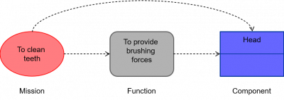
Figure 31 – Standard representations of static elements
Note finally that static elements can occur at different abstraction levels that do also correspond to different integration levels, resulting both in an abstraction and an integration hierarchy. Hence it is always crucial to be able to specify how different types of static elements are connected altogether by such relationships. The standard representations of these abstraction / integration relationships is provided by the below Figure 32, where we also put the associated allocation relations (beware that arrow ends, which express relationships, are squared when dealing with components).
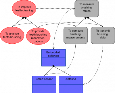
Figure 32 – Standard representations of integration relations between static elements
For the sake of completeness, one also needs to explicitly represent the full integration mechanism that relates the different static elements of lower level that are abstracted by a static element of higher level (see Definition 0.5). Figure 33 below shows an example – in the line of Definition 0.5 – of standard representation of such an integration mechanism – where oriented arrows labelled with an exchanged flow represent interfaces6We recall that an interface between two static elements E and F is formally nothing else that the couple (E, F). With such an interface, one may associate both flows exchanged between E and F and flows exchanged between F and E (we refer to the Flows subsection that follows for more detailed information on flows). – between different constructional components of the same level of abstraction (here the head, body and embedded system that are forming the “brush” part of an electronical toothbrush). Similar representations do also exist with functions or missions.
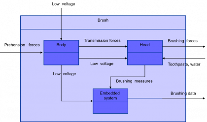
Figure 33 – Interfaces standard representation
Next page