6.1 How to Understand How is Formed the System?
Constructional architecture, or equivalently constructional analysis, intends to describe precisely the different components of a system, but also all their relative interactions1And also how these components are connected both to missions and functions. This point – even if important – will however not addressed in this pocket guide since it can be easily managed through suitable allocation matrices.. The core motivation of constructional architecture is to concretely understand and specify in details the system, in terms of structure – i.e. in other terms, to understand how is formed the system – and not of behaviors, i.e. in its constructionally nature … as one would have naturally guessed!
Constructional architecture is key since it consolidates all architectural analyses in a concrete vision of the considered system. It makes in particular the synthesis between a top-down design approach, as provided by the systems architecting process, and a bottom-up one, which is typically induced by the constraints due to the existing product architecture or by the new possibilities brought by the advances of technology. All the idea of constructional architecture is thus to find the best possible balance between these two apparently contradictory, but in reality completely complementary, approaches. As a consequence, constructional architecture intends to solve a “simple” – to state, but not to solve – multi-dimensional optimization problem: “what is the best concrete architecture – i.e. suitable components with their organization – which answers to the stakeholder needs (top-down approach) while integrating all industrial and technological constraints & opportunities (bottom-up approach), within classical cost, quality, delay and performance objectives?”2 It is always important to be able to state property any constructional architecture problem using such a pattern. This problem is of course highly non-trivial and highly complex in practice due to its large number of parameters and variables. The motivation of constructional architecture is – quite modestly – to propose some key tools that may contribute to that objective.

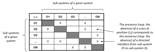
Figure 53 – Design Structure Matrix (DSM) of a system
Constructional architecture also allows to integrate “by design” some important key architectural principles within a system. The best way to prevent the propagation of a local problem throughout a system and its transformation into a global problem, is for instance to organize the system as an integration of decoupled sub-systems, i.e. with minimal mutual interfaces. This property can be easily depicted on the Design Structure Matrix (DSM) associated with a given system S – see Figure 53 – where one indicates a connection from a sub-system Oi of S to another sub-system Oj of S if and only if there is a directed interface from Oi to Oj: minimizing the interfaces of S therefore means finding a constructional decomposition minimizing the number of elements of such a matrix.
Last, but not least, one must point out that constructional architecture is the main input of a series of important engineering activities such as specialty engineering analyses, safety analyses, verification and validation, that we will however not develop here (see [42], [43], [44] or [66]).
What happens when a System has not a Decoupled Constructional Architecture: the Fighter Aircraft F/A-18 Case3The author is grateful to Professor Olivier de Weck (MIT, USA) who told him this case study
The standard aircraft F/A-19 is a fighter & attack aircraft that was developed by McDonnell Douglas for the US Army in the late seventies. It was designed for being aircraft carrier based, supporting 3,000 flight hours, 90 minutes average sorties and 7.5 g positive maximal accelerations and having 15 years of useful life. In the early nineties, the Swiss Army decided to acquire this aircraft. However due to its geographic and politic specificities, Switzerland had very different requirements. First due to their neutrality policy, they did not wanted a fighter, but an interceptor aircraft. Since Switzerland does not have any sea (Leman lake does not count for one …), it was demanded to have a land based aircraft. Swiss people do also like that their belongings last a long time, so they requested their aircraft to support 5,000 flight hours with a 30 year useful life. Finally one shall remember that Switzerland is a very small country with mountains to avoid during each sortie, which lead to be able to support on one hand 40 minutes average sorties and on the other hand 9g positive maximal accelerations.
When McDonnell Douglas engineers analyzed these demands, it was quickly understood that the US version of the F/A-18 could easily respect the Swiss requirements as soon as its less resistant fatigue components were replaced. A deeper analysis showed them that it was even sufficient to replace a few – weighting ≈ 500 grams – structural aircraft parts made in Aluminum by equivalent components made in Titanium (which is much more robust). Unfortunately when this – apparently quite small – change was done, the center of gravity changed which required stiffening the fuselage and increasing the gross takeoff weight to rebalance the aircraft. Due to that various changes, the weight distribution evolved within the aircraft, impacting the flight control software which was necessary to redesign. Various other changes occurred and at the very end, the industrial construction processes and the associated plant were even highly impacted, leading to a 10 million $ overall cost for a little initial change of less than one kilogram … Well decoupling a system’s constructional architecture is therefore crucial!
Case study 8 – The Fighter Aircraft F/A-18 Case
TABLE OF CONTENTS
REFERENCES
[42] IEEE, IEEE 1220-2005 – Standard for Application and Management of the Systems Engineering Process, Institute of Electrical and Electronics Engineers, 2005
[43] INCOSE, Systems Engineering Handbook, A guide for system life cycle processes and activities, INCOSE, January 2011,
[44] ISO/IEC/IEEE, ISO/IEC/IEEE 15288:2015 – Systems and software engineering — System life cycle processes, May 2015
[66] NASA, Systems Engineering Handbook, 2007-edition, NASA/SP-2007-6105, 2007