2.4.2.3 Dynamics
The dynamic of a static element of a system S refers to its temporal behavior or equivalently to an algorithmic description of such a temporal behavior. Dynamics are completely crucial if one wants to precisely specify the behavior of any system or any system mission, function or component.
There are therefore logically three different types of dynamics for a given system S, depending on the considered architectural vision, which are defined as follows:
- Operational dynamics are called operational scenarios: an operational scenario of S is an algorithmic description of the interactions existing between the system (considered as a black box) and its environment,
- Functional static elements are called functional scenarios: a functional scenario of S is an algorithmic description of the interactions existing on one hand internally between the functions of S and on the other hand externally with the environment of the system,
- Constructional static elements are called constructional scenarios: a constructional scenario of S is an algorithmic description of the interactions existing on one hand internally between the components of S and on a second hand externally with the environment of the system.
Note that these three types of scenarios have exactly the same nature since they are all describing an exchange algorithmic. The only difference comes here from the nature of the exchanges that are described by these different scenarios.

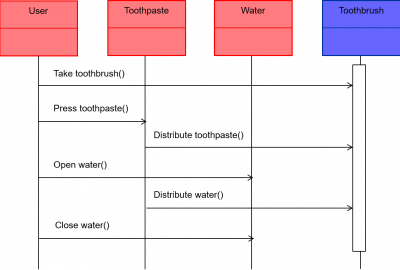
Figure 34 – Standard representations of an operational dynamic
Let us now end by addressing the question of the standard representations of the different types of dynamics which are typically given – in most modeling languages – by sequence diagrams. Figure 34 depicts this formalism with an example of operational dynamic description, here the initiation of a toothbrush use where one specifies the interactions existing between all involved stakeholders and the system. Sequence diagrams provide indeed an efficient and classical formalism for representing distributed algorithms (see [20] for more details). In this mode of representation, the different elements in interaction are positioned on the top of the diagram and each of them has a timeline going from top to bottom that represents time (each element having its own time). One models then an interaction by putting – one after the other – arrows, going from the initiator to the receiver of an interaction between two elements, with an indication either of the function, used by the interaction initiator to manage the interaction, or of the flow which is exchanged during the interaction (see our next subsection for more details). These arrows are thus following the sequential order of a given interaction, as depicted in Figure 34. Note finally that one indicates the interacting sequences that are highly coupled by a large rectangle at the level of the modeled system.
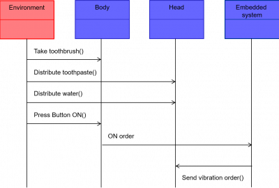
For the sake of completeness, we also provide an example of constructional scenario that can be found in Figure 35 below which represents the exact constructional counterpart of the previous operational scenario. Functional scenarios are represented exactly in the same way, components being just replaced by functions. Note that the difference between a functional or constructional scenario and an operational scenario is only that the environment is a black box in the first situation when it is the case of the system in the second situation1There are of course also mixed scenarios where one may provide details on both the environment and the system..

Figure 35 – Standard representations of a constructional dynamic
2.4.2.4 Flows
A flow associated with a system S models an object – matter, energy, data, information, etc. – which is exchanged either externally between the system and its environment, or internally between two functional or constructional elements of the system.
Flows may be quite different depending on the vision. To illustrate that last point, let us take the example of a traffic light system. When the traffic light is red, it operationally sends a stop request to the drivers that are looking at it. The operational flow exchanged between the traffic light and the drivers can then be modeled by a “STOP ORDER” flow. On the functional level, one would however typically say that the traffic light is just sending red light (which is interpreted as a stop signal by the drivers) to its environment, which may be modeled by a “RED” functional flow. Finally it is amusing to observe that at constructional level, the red color is just produced by lighting the first (starting from the top) white traffic light, in connection with a red filter. The associated constructional flow can thus be modeled by “WHITE 3” to express that situation.
There are therefore logically three different types of flows for a given system S, depending on the considered architectural vision, which are defined as follows:
- Operational flows or objects: an operational flow or object of S is an object that is exchanged between S and its environment, i.e. between S and one of its external system,
- Functional flows or objects: a functional flow or object of S is an object which is an input or an output of one of the functions of S, i.e. which is exchanged between the functions of S,
- Constructional flows or objects: a constructional flow or object of S models a concrete object which is exchanged between the components of S.
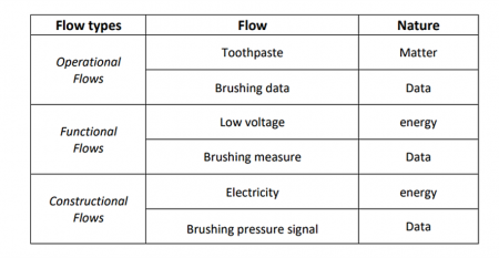
Flows are usually simply stated using only names that are referring to concrete objects which are exchanged between different systems. Table 4 below illustrates these various notion of flows with some examples for an electronic toothbrush.

Table 4 – Examples of flows for an electronic toothbrush
Note that flows are naturally related by allocation relations. As illustrated by the traffic light system example provided above, an operational flow OF may be allocated to either a functional flow or a constructional flow which may be operationally interpreted as OF. In the same way, a functional flow FF may also be allowed to a constructional flow that may be functionally interpreted as FF. Flows hierarchies are therefore naturally induced by these allocation relations. Let us end by providing the standard representations of the three different types of flows – in most modeling languages – which are modeled by “objects” or “blocks” in the usual meaning given to this concept in object-oriented modeling (see [20] or [34]).

Figure 36 – Standard representations of flows
2.4.3 Expected Properties
As already stated above in section 0.3, expected properties are formally speaking logical predicates related with the system of interest (see Chapter 0 or Appendix A for more technical details on that core logical concept that goes back to Aristoteles). An expected property is thus nothing else than a Boolean function2This is thus also true for needs and requirements according to the definitions that follow., i.e. a function P that maps a system on TRUE or FALSE, depending whether the property that P models is satisfied or not by the system:
P: S → P(S) ∈ { FALSE, TRUE }
This consideration allows avoiding confusing expected properties with their constitutive elements. An expected property indeed typically expresses that a given system shall behave or be structured with a certain external or internal performance3In other terms, expected properties do express the performances that shall be satisfied by the system of interest or by its environment, depending whether one deals with the functional/constructional or operational visions. . The involved behavioral or structural elements & performances shall thus not be mixed with the property, since they are just not logical predicates.
It is also important to remember that one can analyze in practice a given system S from an external or from an internal perspective. This consideration leads to the key distinction between needs & requirements, which are the two first main types of expected properties on S:
- External perspective4External perspective is here a synonym of operational vision. – Need: a need with respect to S is a property that is expected or imposed by the environment Env(S) of S, expressed in the language of the environment5 One cannot thus use the language of the system to express a need. (i.e. only referring to operational descriptions & performance),
- Internal perspective – Requirement: a requirement on S is a functional or constructional property that shall be satisfied by S, expressed in the language of the system (i.e. only referring to functional or constructional descriptions & performances).
One shall of course understand that these definitions are fundamentally relative to a given system. A need with respect to a system S is indeed a requirement on the environment Env(S) of S. In the same way, a requirement on S is also a need with respect to a subsystem of S. One should hence always remember to point explicitly out the system of interest to which refers any need or requirement. Note also that we used here above a voluntarily different terminology depending on the external or internal perspective we may take with respect to expected properties. A good system architecting practice indeed consists in strictly separating the domain of the question – expressed using needs – from the domain of the solution – expressed by means of requirements6This point is illustrated by Case study 4.. In other terms, needs shall be only reserved to model questions, when requirements shall model the corresponding answers. This point is crucial since many engineering problems are due to the fact that stakeholders are often expressing their “needs” in an intrusive way, i.e. in terms of requirements in our meaning. This bad practice both limit the ability of the designers to propose better alternative solutions and prevent them to know the real needs hidden behind requirements7In a recent customer specification file for military vehicles, one could for instance find the demand C ≡ “The vehicle shall be painted in green” which was just copied/pasted from previous files. This expected property is typically not a need, but a constructional requirement. A good systems architect shall then try to understand the functional & operational expected properties from which C derives. In this case, C can be traced back to a functional requirement F ≡ “The vehicle shall not be visible”, itself coming from a quite simple need N ≡ “Soldiers shall not die when in operations”. At this point, one now has the rationale of the green color which was just motivated by the fact that it allows to be invisible in European battlefields when green is dominant. But conflicts are not anymore taken place in Europe, but rather in Middle East or Afghanistan where ocher and sand colors are dominant. The analysis of the root need allows thus to understand that C is a very bad constructional choice to implement the functional requirement F which is still valid. One shall of course rather request C’ ≡ “The vehicle shall be painted in ocher/sand colors”, which could not be suspected if only staying at constructional level., which may ultimately lead to bad solutions from an end-user perspective even if fitting perfectly to their requirements.
Note finally that requirements on a system S can be of course refined into two sub-types depending whether one is dealing with functional or constructional visions:
- Functional requirement: a functional requirement on S is a property that shall be satisfied by the behavior of S, expressed in the functional language of the system (i.e. only referring to functional descriptions & performances),
- Constructional requirement: a constructional requirement on S is a property that shall be satisfied by the structure of S, expressed in the constructional language of the system (i.e. only referring to constructional descriptions & performances).
To write down properly these different types of expected properties, one shall use the standard statement patterns – referring to the notions introduced above – that are provided in Table 5.
| Need | The “external system8Or equivalently a stakeholder of the system (see Chapter 3). ” shall “do something / be formed of something” with a certain “operational performance” in a given “operational context”. |
| Functional requirement | The “system” shall “do something9“To do something” shall always refer here to an existing function of the considered system. ” with a certain “functional performance” in a given “functional mode”. |
| Constructional requirement | The “system” shall “be formed of something10“To be formed of something” shall always refer here to an existing component of the considered system.” with a certain “constructional performance” in a given “configuration”. |
Table 5 – Standard statement patterns for needs and functional & constructional requirements
Table 6 illustrates the three previous different types of expected properties – written in accordance with the above standard statement patterns – on an electronic toothbrush, with a picture of the toothbrush part which is (partially) specified by them. In this example, the proposed need was derived first into a functional requirement that was derived then into a constructional requirement. One can thus immediately trace back here the last constructional choice to the associated service provided to the end-users, which is useful – especially to analyze the stakeholder value brought by a given technical decision – since this service cannot be seen at constructional level.
| Need | End users shall get a positive11Positive refers here to the performance. feeling when efficiently cleaning their teeth. |
| Functional requirement | The electronical toothbrush shall display an encouraging message within 1 second when cleaning performance has been met. |
| Constructional requirement | The electronical toothbrush shall have a user interface of 2.5 cm x 1cm in each configuration. |
Table 6 – Examples of expected properties per architectural vision
Note finally that the previous types of expected properties are complete by construction with respect to the CESAM framework. In other words, one can always specify any system in intension by using only needs, functional requirements and constructional requirements, without anything else.
Needs or Requirements? The Tanker Case
In the 70’s, important leaks occurred when pumping out liquid natural gas from tankers. The issue was that dangerous cracks appeared in the shell of the tankers due to the very cold temperature – closed to 0°K – of the gas. To solve that problem, engineers began to think in terms of technical solutions which lead to a strong requirement on a metal for tankers shells that should not crack at liquid gas temperature. This was however a very bad idea since the resulting solution would probably have requested many years of R&T and cost hundreds of millions euros.
Another way of reasoning is to express the problem in terms of the question to solve, which is “how to avoid the gas to enter in contact with the shell metal?” Such a question expresses a simple constraint on the gas (which is a need in CESAM formalism) that has to be fulfilled. Such a question has then a simple and quite cheap solution, consisting in putting pieces of folded cardboard under the leaking points. The gas is then retained by the cardboard before quickly evaporating, which avoids all troubles.
As one sees on that illustrative simple example, there may be a huge gap between thinking in terms of solutions (requirements) and in terms of questions (needs).
Case study 4 – Needs or requirements? The tanker case
There is in particular no need to introduce the concept of “non-functional requirements” that exists in many other architectural referential (cf. [42], [43] or [44]) and does often refer to “ity” properties of a system such as availability, maintainability, operability, safety, reliability, security, etc. All these properties can indeed easily be expressed in terms of needs. To be more specific, let us take the example of a maintainability property for a given system which would probably be expressed by most engineers by stating that M ≡ “the system shall be maintainable”. However “To be maintainable” can clearly not be considered as an internal function of a system since it does not refer to any input/output behavior, but rather to a permanent status of the system. Property M is therefore neither a functional, nor a constructional requirement12 Since it also obviously does not directly refer to a property of the components of the system. , nor a need13Strictly speaking, it indeed only refers to the system and not to its environment. within our framework. It has thus absolutely no status at all, which shows that it is probably a bad specification! The good way of expressing the property M is then just to identify the hidden stakeholders behind – which are here just maintenance teams – and to understand what are expecting these stakeholders. In our example, this would lead us to reformulate M by stating instead M’ ≡ “the maintenance teams shall maintain the system with a certain performance”14 Which is now correctly written since “To maintain the system” is clearly a behavior of the maintenance teams. which is now obviously a need since it expresses an expectation of the environment of the system. The reader can do the same kind of exercise for the other classical “non-functional properties” of a system to convince him/herself that all theseproperties are just bad formulations of needs15Availability, operability, safety, reliability or security issues do for instance typically refer to customers, end-users and/or operators expectations..
Next pageTABLE OF CONTENTS
REFERENCES
[20]Booch G., Jacobson I., Rumbaugh J., The Unified Modeling Language Reference Manual,Second Edition, Addison-Wesley, 2004
[34] Friedenthal S., Moore A.C., Steiner R., A Practical Guide to SysML : the Systems Modeling Language, Morgan Kaufmann OMG Press, 2012
[42] IEEE, IEEE 1220-2005 – Standard for Application and Management of the Systems Engineering Process, Institute of Electrical and Electronics Engineers, 2005
[43] INCOSE, Systems Engineering Handbook, A guide for system life cycle processes and activities, INCOSE, January 2011,
[44] ISO/IEC/IEEE, ISO/IEC/IEEE 15288:2015 – Systems and software engineering — System life cycle processes, May 2015