2.2.2 Feature 2: Iterative Collaboration between Layers and Disciplines
The second idea of our agile approach for complex systems engineering consists in iteratively defining the product by organizing its development into successive collaborative design loops of increasing length and granularity where the product relevancy, consistency and feasibility is assessed at more and more precise levels of analysis (see next figure). Each loop shall in particular cover and study several possible product variants at different levels of grain along their full development cycle, starting from top-level architecture up to manufactured part design and definition of manufacturing and maintenance concepts. The design choices shall be gradually frozen and deepened until achieving the full complete specification of the product and of its associated manufacturing and maintenance processes. All system stakeholders – in particular manufacturing & maintenance actors – shall be involved in these design loops in order to capture as early as possible their constraints. Such a development model makes it possible to freeze quickly structuring choices related to system global performance, system architecture, external or internal interfaces, critical parts or technologies and development, manufacturing & maintenance processes, ensuring the technical and industrial feasibility of the target system and providing a good control of risks at any time.
During each design loop, all involved teams – that is say all engineering & manufacturing disciplines involved in a given product development – shall work collaboratively and share the same set of design drivers and hypotheses that will be progressively refined and frozen (see enabler 3). At the end of each design loop, a new product increment shall be generated through relevant models and tools (see enabler 4). Due to the progressive refinement of the design drivers, this approach provides a huge adaptability of the development process to new or updated requirements or constraints coming from various stakeholders. This approach also helps multidisciplinary teams to reach the global optimum choice of the product at each loop. The below Figure 3 illustrates such an approach with three design loops starting from a coarse grain high-level loop up to a fine grain detailed loop.
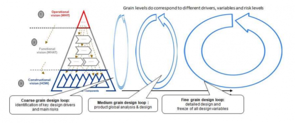
Figure 3 – Our agile development model based on successive and more & more detailed design loops
Each design loop will then analyze a number of design alternatives, starting typically with a dozen alternatives in the first loop, reducing them to 2-4 main alternatives in the second loop, up to converging to only 1-2 key alternatives in the last loop. This can be achieved by using trade-offs techniques, with different levels of details to reach a global optimum (see the below Figure 4).
Note that requirements are usually often over-specified and in much too important number, due to the fact that all actors in the development chain are creating requirements to protect themselves by taking local margins of security. In an agile approach, each design loop shall therefore pay a specific attention to formalize the system requirements to what is just necessary: this objective relies on prioritization techniques managed through collaborative requirements reviews, involving regularly all key development actors, where allocations of performance are collaboratively managed and optimized when descending into product architecture.
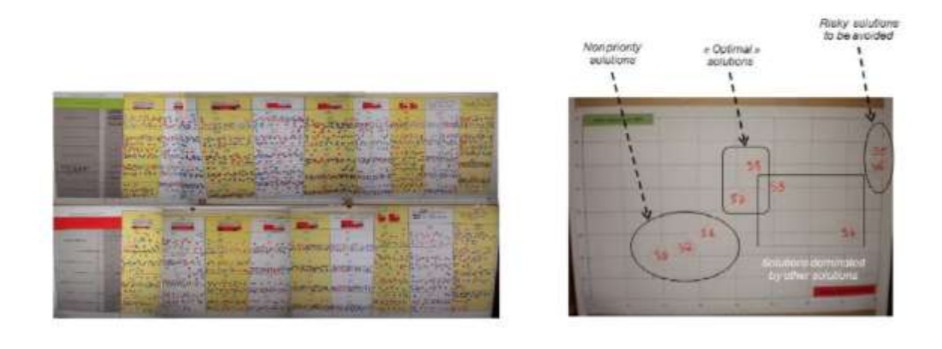
Figure 4 – Examples of several architectures compared through a Pareto multi-criteria optimization approach
Since we are dealing with systems, any agile development process shall also take into account deeply the constraints coming from manufacturing and maintenance since these are the steps where the “real thing” is constructed and used. In an agile systems engineering process, manufacturing teams must therefore be involved in each design loop – as already pointed out previously – in order to analyze design requirements from their perspective and to evaluate/simulate their impact on manufacturing and assembly processes with the “good” industrial KPIs (e.g. lead time, NRC & RC). Similarly support & services teams must be involved in order to evaluate the impact of design requirements on the maintenance processes using relevant KPIs (e.g. time and cost of maintenance operations).
Regular rituals, involving design, manufacturing and maintenance teams, and more generally all relevant stakeholders, shall therefore be regularly organized within each design loop in order to integrate all these different point of views in the design. Model-based systems engineering plays a key role in these rituals since they shall be balanced between a product and a project focus. A typical agile design ritual indeed consists in examining and discussing collectively more and more precise models of the product under development (see an automotive example in the next figure).
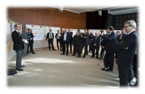
Figure 5 – Example of a development ritual using model-based representations of a complex system
2.2.3 Feature 3: Iterative Key Design Driver’s Management
The third key idea is the preliminary identification of the key design parameters on which each design loop rely. They shall form for each design loop a coherent set of interdependent characteristics, dealing with either product environment (e.g. mission profiles, use cases, customer & stakeholder requirements), either functional (e.g. presence of specific functions, behavioral performance) or constructional (e.g. mass, geometry of critical parts, technology) requirements, or manufacturing & maintenance constraints. These key design drivers also allow to explore design space and to identify potential architecting variants. The first loop focuses for instance on the structuring parameters of the product to analyze with highest priority. Note finally that these drivers can be derived from the analysis of a stakeholder need and functional & constructional requirement architecture, which are thus the first key models on which relies our agile approach.
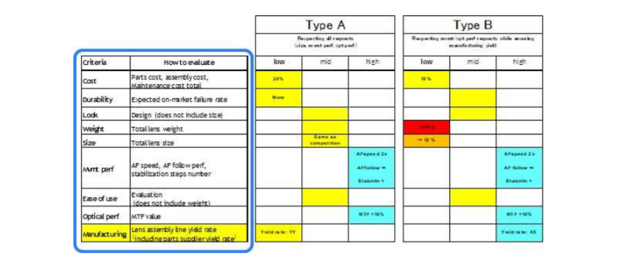
Figure 6 – Examples of design drivers identified in the context of an innovative camera development, here used to define two product variants that were analysed during a first design loop
The Key Design Drivers (KDD) represent the hypotheses shared between all teams involved in an agile development, i.e. the shared design space. During a given design loop, teams work with a fixed range for each KDD, with freedom of design while their parameters are contained into the defined ranges, from each synchronization ritual to the next one. At each iteration, teams define and evaluate potential architecture variants within KDD ranges in order to progressive reduce these ranges at the end of the iteration. If no feasible architecture can be defined within the design space defined by the current KDDs, a synchronization activity will redefine new KDD ranges.
This approach ensures agility to adapt the design in a robust way by mastering the traceability from initial stakeholder requirements to shared design functional & constructional hypotheses.
2.2.4 Feature 4: DMU and FMU as Pivots for Transversal Synchronization
The last ingredient of an agile systems engineering process is to use Digital & Functional Mockup (DMU and FMU) as pivots for transversal synchronization in each design loop. The key idea is that at the end of each iteration, each team shall produce models (3D, thermal, mechanical resistance, thermodynamics, etc.) which are to be integrated in a shared DMU (for the geometrical aspects) and in a shared FMU (for the functional aspects), whose overall coherence is analyzed. Due to the need of synchronizing all disciplines at each product increment, the use of these digital models as pivots for the design is therefore key to support an agile approach.
Note that usually the functional digital mockup is not a single tool, but rather a series of interconnected tools (e.g. Capella, Simulink, FL Editor, etc.). A key difficulty is here to ensure the alignment of the system decomposition used in the functional digital mockup with the geometrical decomposition on that the digital mockup manages, which currently is still a matter of human expertise. Both tools have indeed different modeling constraints and traditionally have been imposed separately. Nevertheless, to implement agile engineering, functional and discipline integration through both functional oriented design tools and CAD is a key enabler.
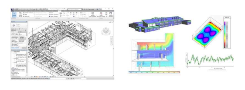
Figure 7 – Illustrations of Digital and Functional Mockup views
A key point is also that the FMU shall be designed to provide comprehensive system level predictive models, that is to say models integrating all key product dimensions, typically of multi-physical nature, that allow to simulate the system under design within its environment in order to validate hypotheses and manage trade-offs. The levels of detail and the representativeness of such models must necessarily be aligned with the granularity of the design loops. These models can be existing models (e.g. Simulink / Modelica models) or existing model aggregations via ad hoc tools (e.g. Optimus). Such system level simulation models are in particular key for evaluating design performances, validating the design choices, managing the initial trade-offs and helping to negotiate the customer.
next page